Timer/Counters
- Increment based on
- Timer: regular clock pules
- Counter: Irregular event pulses
Implementation
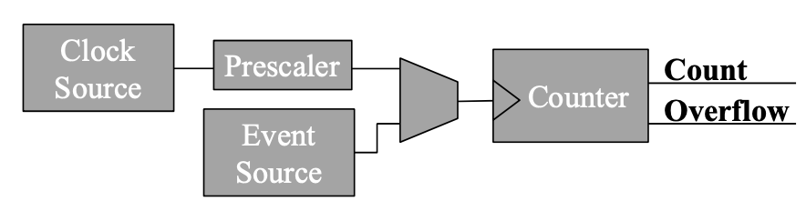
- Mux allows toggling between timer (regular) and counter (events)
- Prescaler
- Timer is limited by size of counter register (how many bits) and rate at which counter changes (update rate)
- A prescaler modifies the standard timer clock update rate
- Forces a tradeoff between resolution and range
- Important for smaller 8 and 16 bit counters
Types
- Output Compare
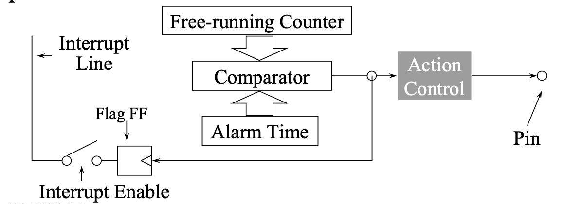
- Trigger when counter hits a target value
- Like an alarm
- Input Capture
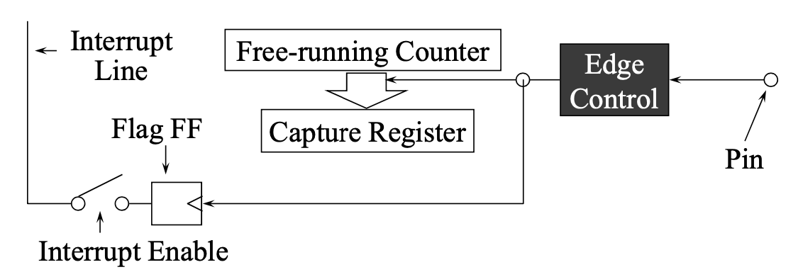
- Only have the capture increment alongside the counter when the input is true
- Like a stopwatch
Terminology
- BOTTOM: When the counter reaches zero
- MAX: The counter reaches MAXimum (all ones)
- TOP: The counter reaches TOP when it becomes equal to the highest value in the count sequence
- The TOP value can be equal to the period (PER) or the compare channel A (CCA) register setting
- This is selected by the waveform generator mode
- UPDATE: The timer/counter signals an update when it reaches BOTTOM or TOP, depending on the waveform generator mode
XMEGA Registers
- All prefixed with
TCpx_ to tell which timer it is for
p is the port it outputs tox is the timer number
CTRLA controls the clock sources for timersCNT
- Count register is incremented or decremented every clock cycle (possibly modified by a prescaler)
- Used by TC module to perform compare/capture operations
- May be read from or written to
PER
- Period register holds the
TOP value for CNT
- In XMEGA, Can be modified when running, but will not immediately reset if already passed the new value
CCx
- Compare/Capture Registers
- In Capture mode, if a capture event is triggered, the current CNT value is loaded into the enabled CCx register
- In Compare mode, the CNT register is constantly compared to the CCx registers
- Writing
- Use
___L and ___H for low and high bytes
- Must write the low byte first
INTFLAGS
- Register to hold
CC, Error, and Overflow/Underflow flags
- To clear, write a 1 to the flag bit
Pulse Width Modulation
- Method of controlling analog circuits with digital outputs by delivering energy through a sequence of pulses
- A signal (square wave) is generated by controlling when to turn a digital signal on or off
- Duty cycle = ratio of high time to low time
- Can be used to control RGB LEDs by setting each RGB percent to be the duty cycle