Finite State Automata
Mealy Automata
- A tuple A=(X,Y,S,δ,λ,s1)
- X: Finite, non-empty set of input symbols
- Y: Finite, non-empty set of output symbols
- S: Finite, non-empty set of states
- δ:S×X→S (state transition function)
- λ:S×X→Y (output function)
- s1: Initial state
- Outputs are linked to the edges
State Transition Table
- Table in which the rows represent states and columns represent input symbols
- An entry (δ(s,x)/λ(s,x)) captures the transition from state s∈S with the input symbol x∈X to state δ(s,x) with output λ(s,x)
State Transition Graph
- A state transition graph is a directed graph in which nodes represent states and edges represent transitions
- Edges are labeled with the values of the transition function
- The node without precedence is the initial state
Categories
- Deterministic if: ∀x∈X,∀s∈S:∣δ(s,x)∣≤1
- Not more than one option for a given input at each given state
- Complete if: ∀x∈X,∀s∈S:∣δ(s,x)∣≥1
- Both: ∀x∈X,∀s∈S:∣δ(s,x)∣=1
- We limit ourselves in this class to deterministic and complete
- Non-complete automata model incomplete specifications
- Non-deterministic automata are used in analysis and verification of sequential circuits
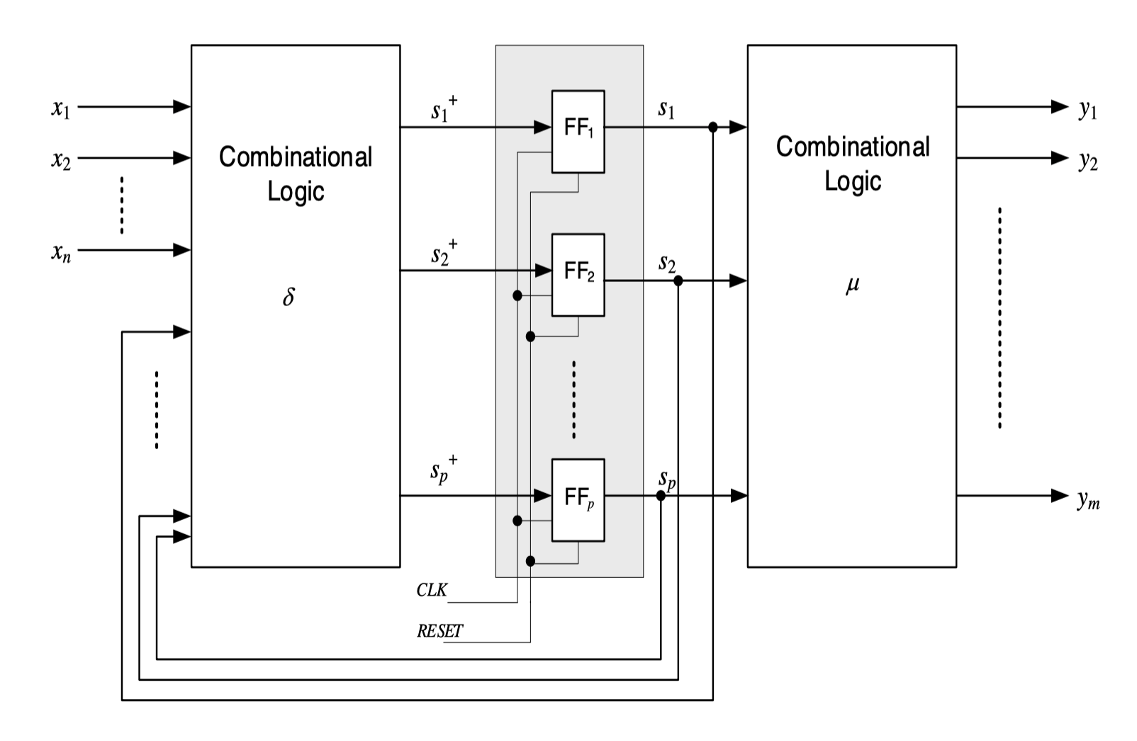
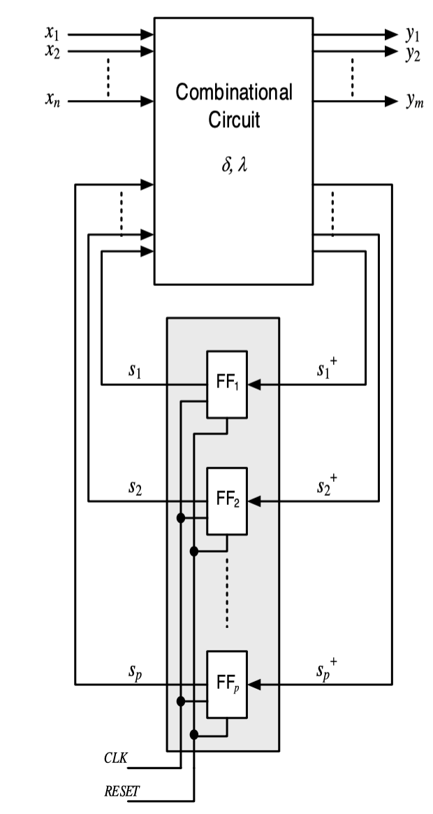
Hardware Implementation
- Finite state machines = technical realization of automata
- Structured using huffman normal form
- Symbols X, Y, and S are binary coded
Moore Automata
- A tuple A=(X,Y,S,δ,μ,s1)
- X: Finite, non-empty set of input symbols
- Y: Finite, non-empty set of output symbols
- S: Finite, non-empty set of states
- δ:S×X→S (State transition function)
- μ:S→Y (Output function)
- s1: initial state
- The output Y depends only on the current state, not the input
- So the input is linked to the nodes
- The output function is also known as state marking function
Hardware Implementation
Design
- Specify the automaton using state transition table/graph
- If needed, minimize the number of states
- Compute binary coding of the inputs and outputs. Compute the number of memory cells needed to store the states
- Specify the combinational circuits for the functions δ and λ or μ from the state transition table. S+=δ(X,S) and Y=λ(X,S) or Y=μ(S)
- Design of the Combinational Logic as Two Level Logic or multi-level logic
Conversion
- Moore to Mealy
- Mark transitions to a state with the output linked to that state
- Reduce
- Mealy to Moore
- For each state s of the mealy automaton, insert as many states as there are incident edges to s
- Label the new states with the output variables of the corresponding incident transitions
- Reduce
Comparison
- Have the same modeling power
- Moore automata need more states in general than mealy
- Output
- Moore: change only upon state transition
- Mealy: change with inputs
- Moore automata are more robust to short impulses of the inputs (glitches) and usually preferred to Mealy in hardware design
- Mealy-automata react faster to changes at the input