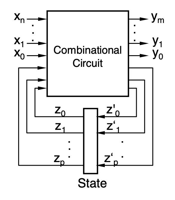
Sequential Logic
- Circuit whose outputs depend on the current and previous inputs
- Memory is required to store the circuit’s state
- The state is the set of all values needed for future computation
- Output = f(previous state, current inputs)
- Used in Memory
- Huffman model
Delays
- Modeling of delays
- Gates and wires have delays
- Only gate delays (propagation delay) are considered in most tools
- Now that transistors are getting smaller, wire delays are starting to matter more → need to use timing closure (accurate timing estimation)
- Inputs and outputs are time-dependent
- Modeling of a real gate is done using an ideal gate and a delay elements
- The output of a gate uses the input values at
- Inertial Delays: Input impulse is too short to have an effect on the output
- Glitches can be observed before the output becomes stable
Definitions
- Latch: Circuit that can store a value (level triggered)
- Flip flop: Bistable but only updates when the clock changes (edge triggered)
- Transparent: Updates the outputs depending on the inputs immediately
- Synchronous sequential: When all sequential circuits update based on the same clock
Latches and Flip Flops
SR-Latch
- Utilizes the propagation delay to have feedback from the previous output

- Forbidden input: (1, 1) because it causes it to oscillate in the step after
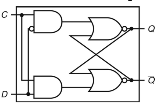
D-Latch (Flip Flop)
- A wrapper around the SR-Latch that writes the data input whenever the clock input is true
- Also eliminates the undefined state (1,1) of the SR-Latch
- Inputs
- D for “delay” or “data”
- C for enable
- Just a D-latch is transparent → Need to add stuff to make it a flip flop
- Making it a Flip Flop
- Master-Slave D-Latch
- Interrupts feedback loop by using two latches serially with complementary enable
- Edge Triggered Latches
- Reacts to signal edge
- Only sets C to true for the short time where the edge detector detects a clock edge
- Notated by replacing C with a sideways triangle
- Master-Slave D-Latch
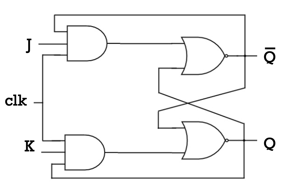
JK Flip Flops
- An extension of the SR flip-flop
- Makes the invalid 1,1 input toggle
| J | K | Q |
|---|---|---|
| 0 | 0 | |
| 0 | 1 | 0 |
| 1 | 0 | 1 |
| 1 | 1 |
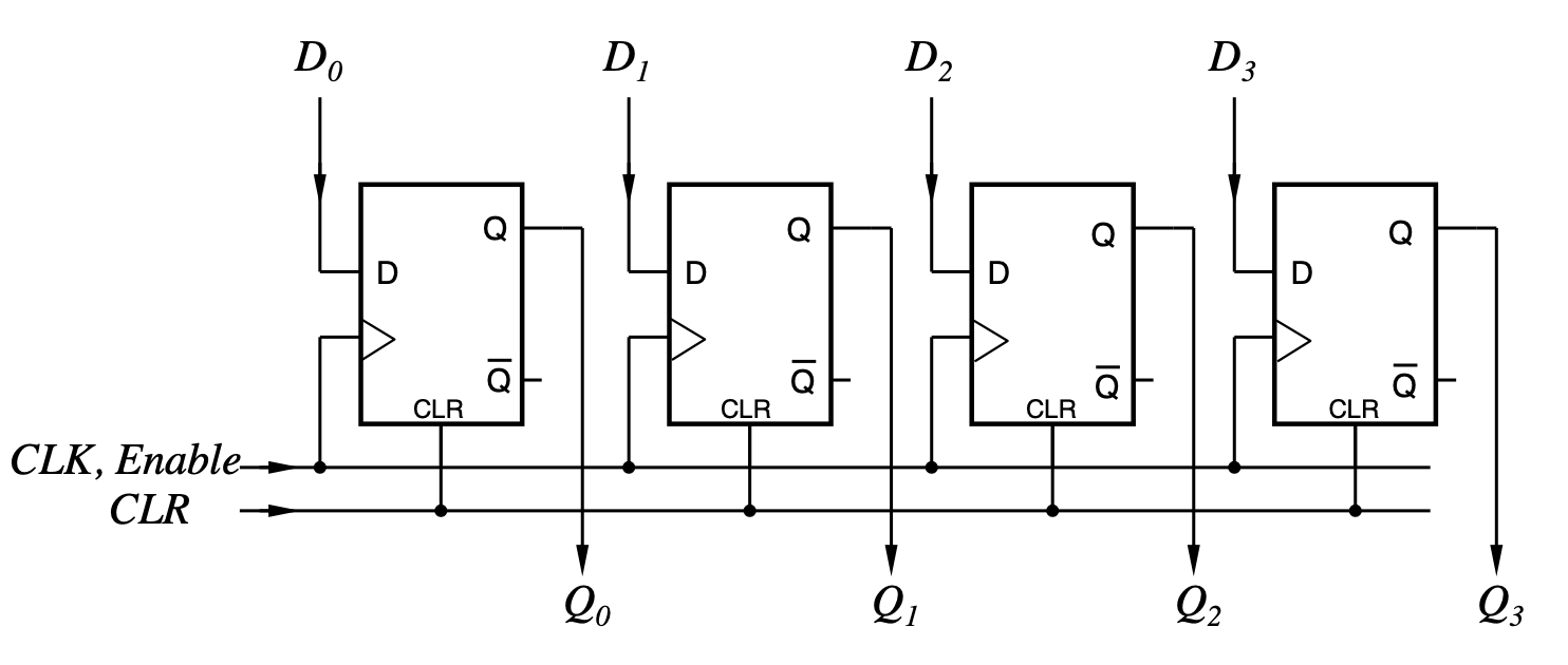
Registers
Parallel/Buffer Register
- a n-bit register consists of n flip flops that can store one n-bit word
- Known as parallel register or buffer register because you read and write in parallel
Shift Register
- A n-bit shift register produces the input value after n pulses
- Have FIFO behavior
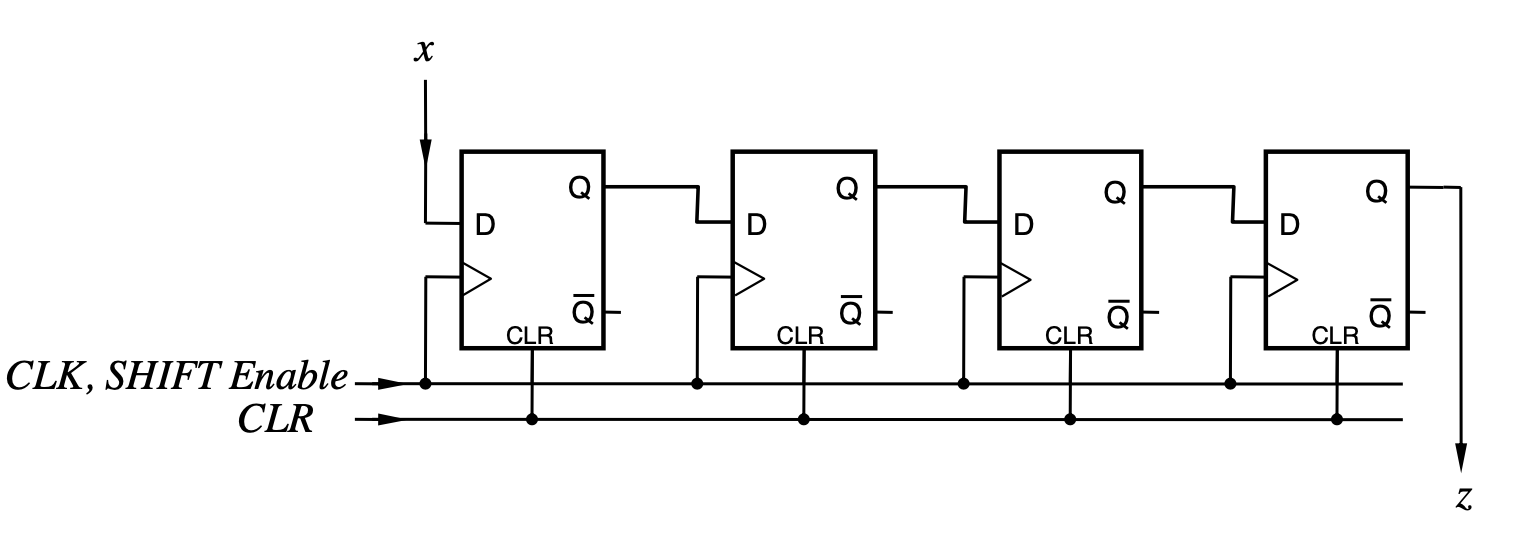
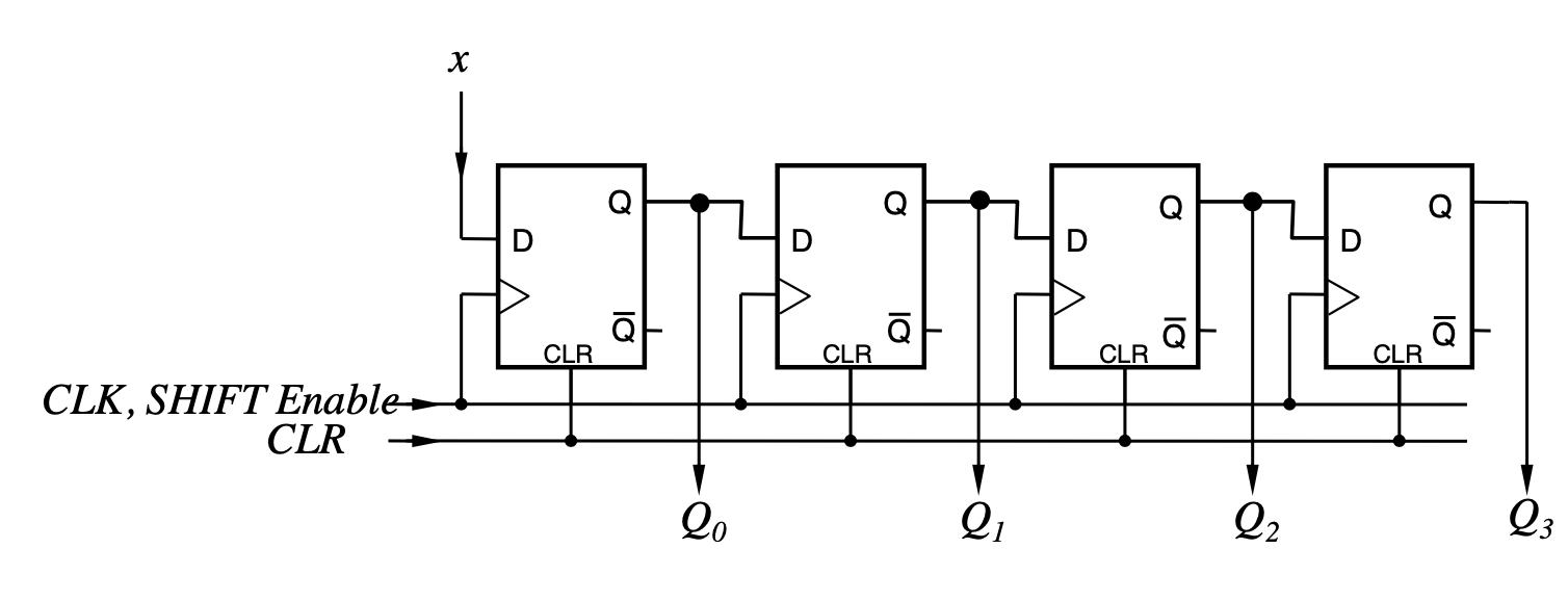
Serial to Parallel Converter
- n-bit shift register in writing and parallel in reading
Counters
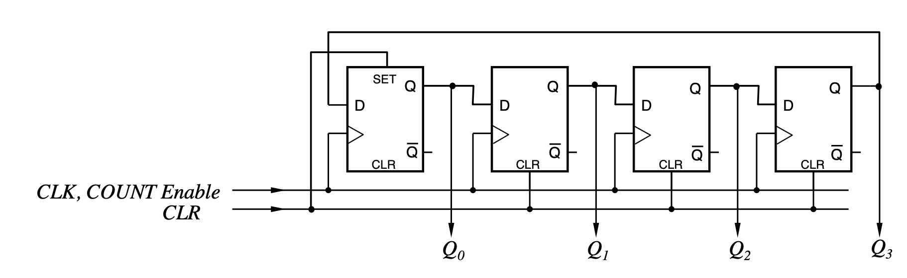
Ring Counter
- n-bit produces powers of 2 up to and then loops
- Can be realized using a n-bit shift register with feedback
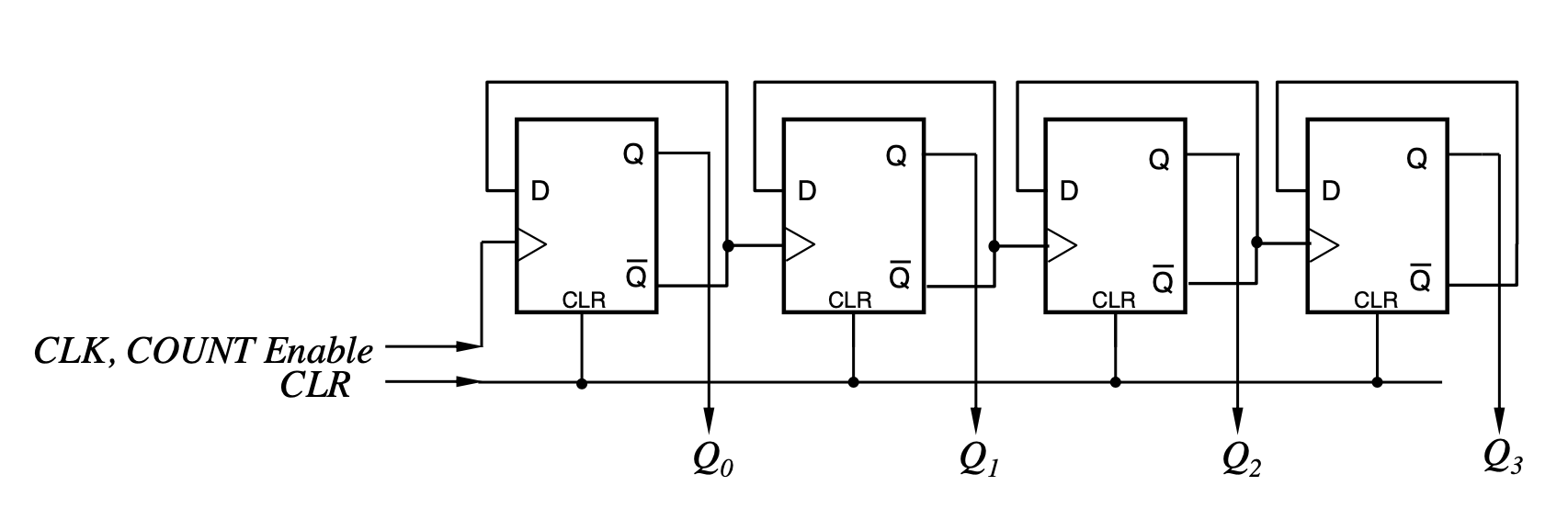
Asynchronous Counter
- Counts from 0 by one, mod
- Each flip flop is clocked with half the frequency of the previous flip flop
- Called asynchronous because all the flip flops are not triggered by the same clock
Synchronous Counter
- Counts from 0 by one, mod (like the async counter)
- However all of the flip flops have an equal clock (this is sometimes a hardware requirement)
- Just stores the current state and then has a combinational circuit calculate the next value
- Follows Huffmann’s model for sequential circuits
- Can be extended to any sequence (just change the combinational logic)